Solar Energy System Design
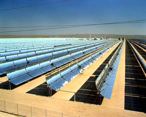
The largest solar electric generating plant in the world produces a maximum of 354 megawatts (MW) of electricity and is located at Kramer Junction, California. This solar energy generating facility, shown below, produces electricity for the Southern California Edison power grid supplying the greater Los Angeles area. The authors' goal is to provide the necessary information to design such systems.
The solar collectors concentrate sunlight to heat a heat transfer fluid to a high temperature. The hot heat transfer fluid is then used to generate steam that drives the power conversion subsystem, producing electricity. Thermal energy storage provides heat for operation during periods without adequate sunshine.
Figure 1.1 One of nine solar electric energy generating systems at Kramer Junction, California, with a total output of 354 MWe.
(photo courtesy Kramer Junction Operating Company)Another way to generate electricity from solar energy is to use photovoltaic cells; magic slivers of silicon that convert the solar energy falling on them directly into electricity. Large scale applications of photovoltaic for power generation, either on the rooftops of houses or in large fields connected to the utility grid are promising as well to provide clean, safe and strategically sound alternatives to current methods of electricity generation.
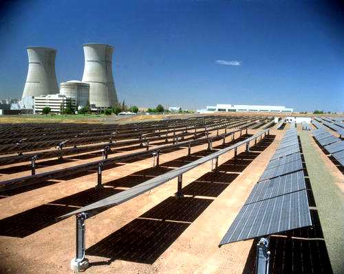
Figure 1.2 A 2-MW utility-scale photovoltaic power system co-located with a defunct nuclear power plant near Sacramento, California.
(photo courtesy of DOE/NREL, Warren Gretz)The following chapters examine basic principles underlying the design and operation of solar energy conversion systems such as shown in Figure 1.1 and 1.2. This includes collection of solar energy, either by a thermal or photovoltaic process, and integration with energy storage and thermal-to-electric energy conversion to meet a predefined load. Study of the interaction of these subsystems yields the important guidelines for the design of optimal solar energy systems. System design tools are provided to produce optimal sizing of both collector field and storage so that optimum system designs can be produced.
Since our emphasis is on the design of entire solar energy conversion systems rather than design of its individual components, both thermal and photovoltaic systems are included. This novel approach results from recognition of the commonality of most system design considerations for both types of solar energy systems. We will not dwell on the intricacies of individual component design, but instead encourage the designer to take experimental (or predicted) component input/output information and incorporate this into an overall system design.
The system shown in Figure 1.1 employs parabolic trough line-focus collectors. We will cover this and other types of collectors for capturing the sun's energy including flat plate, parabolic dish, central receiver and photovoltaic collectors. The purpose of a solar collector is to intercept and convert a reasonably large fraction of the available solar radiation. For solar thermal systems this energy is converted into thermal energy at some desired temperature and then, maybe, into electricity.
For photovoltaic systems as shown in Figure 1.2, intercepted solar energy is converted directly into low voltage direct current electricity. The engineering tradeoff between cost and performance of the components necessary to perform these processes has led to a wide variety of collector and system designs. Reviews of solar collector designs representative of the different concepts that have been built and tested are presented here.
The following sections serve as an overview of the solar energy system design process. They follow in a general manner, the flow of logic leading from the basic solar resource to the definition of an operating solar energy conversion system that meets a specified demand for either thermal or electrical energy.
There are many different types of solar energy systems that will convert the solar resource into a useful form of energy. A block diagram showing three of the most basic system types is shown as Figure 1.3. In the first diagram , the solar resource is captured and converted into heat which is then supplied to a demand for thermal energy (thermal load) such as house heating, hot water heating or heat for industrial processes. This type of system may or may not include thermal storage, and usually include an auxiliary source of energy so that the demand may be met during long periods with no sunshine.

Figure 1.3 Diagram of a basic solar energy conversion systems. The AUX. box represents some auxiliary source of thermal or electrical energy.
If the demand (load) to be met is electricity (an electrical load) rather than heat, there are two common methods of converting solar energy into electricity. One method is by collecting solar energy as heat and converting it into electricity using a typical power plant or engine; the other method is by using photovoltaic cells to convert solar energy directly into electricity. Both methods are shown schematically in Figure 1.3.
In general, if solar energy conversion systems are connected to a large electrical transmission grid, no storage or auxiliary energy supply is needed. If the solar energy conversion system is to be the only source of electricity, storage and auxiliary energy supply are usually both incorporated. If the thermal route is chosen, storage of heat rather than electricity may be used to extend the operating time of the system. Auxiliary energy may either be supplied either as heat before the power conversion system, or as electricity after it. If the photovoltaic route is chosen, extra electricity may be stored, usually in storage batteries, thereby extending the operating time of the system. For auxiliary power, an external electricity source is the only choice for photovoltaic systems.
The basic resource for all solar energy systems is the sun. Knowledge of the quantity and quality of solar energy available at a specific location is of prime importance for the design of any solar energy system. Although the solar radiation (insolation) is relatively constant outside the earth's atmosphere, local climate influences can cause wide variations in available insolation on the earths surface from site to site. In addition, the relative motion of the sun with respect to the earth will allow surfaces with different orientations to intercept different amounts of solar energy.
Figure 1.4 shows regions of high insolation where solar energy conversion systems will produce the maximum amount of energy from a specific collector field size. However, solar energy is available over the entire globe, and only the size of the collector field needs to be increased to provide the same amount of heat or electricity as in the shaded areas. It is the primary task of the solar energy system designer to determine the amount, quality and timing of the solar energy available at the site selected for installing a solar energy conversion system.
Figure 1.4 Areas of the world with high insolation.
Just outside the earth's atmosphere, the sun's energy is continuously available at the rate of 1,367 Watts on every square meter facing the sun. Due to the earth's rotation, asymmetric orbit about the sun, and the contents of its atmosphere, a large fraction of this energy does not reach the ground. In Chapter 2, we discuss the effects of the atmospheric processes that modify the incoming solar energy, how it is measured, and techniques used by designers to predict the amount of solar energy available at a particular location, both instantaneously and over a long term.
As an example of the importance of the material discussed in Chapter 2, Figure 1.5 shows the variation of insolation over a full, clear day in March at Daggett, California, a meteorological measurement site close to the Kramer Junction solar power plant described previously. The outer curve, representing the greatest rate of incident energy, shows the energy coming directly from the sun (beam normal insolation) and falling on a square meter of surface area which is pointed toward the sun. The peak rate of incident solar energy occurs around 12:00 noon and is 1,030 Watts per square meter. Over the full day, 10.6 kilowatt-hours of energy has fallen on every square meter of surface area as represented by the area under this curve.
Figure 1.5 Insolation data from Daggett, California on a clear March day.
The middle curve represents the rate of solar energy falling on a horizontal surface at the same location. For reasons to be discussed later, this curve includes both the energy coming directly from the sun's disc, and also that scattered by the molecules and particles in the atmosphere (total horizontal insolation). This scattered energy is shown as the bottom curve (diffuse insolation). Over the entire day, 6.7 kilowatt-hours of solar energy fall on every square meter of horizontal surface, of which 0.7 kilowatt-hours comes from all directions other than directly from the sun.
Techniques for estimating the temporal solar resource at any site on the face of the earth are presented in Chapter 2. In addition, the development and use of computerized meteorological data files is described. These data files based on long-term actual observations, form the time-dependent database of the computerized performance computations contained within this book and, indeed, much of the solar literature.
An example of a complete set of beam normal insolation data for a given location is shown in Figure 1.6. Here we see hourly insolation data, summarized over a day, for each month of a year. With this type of data for a specific site, it is possible to predict accurately the output of a solar energy conversion system, whether it is a low temperature thermal system, a high temperature thermal system or a photovoltaic system.
Figure 1.6 Time and date description of the global, horizontal insolation solar resource for Cairo Egypt.
In addition to estimating the amount of energy coming from the sun, the solar designer must also be able to predict the position of the sun. The sun's position must be known to predict the amount of energy falling on tilted surfaces, and to determine the direction toward which a tracking mechanism must point a collector. Chapter 3 discusses the computation of the position of the sun with respect to any given point on the face of the earth. Using only four parameters (latitude, longitude, date and local time), equations are derived to determine the location of the sun in the sky.
A characteristic fundamental to the capture of solar energy is that the amount of energy incident on a collector is reduced by a fraction equal to the cosine of the angle between the collector surface and the sun's rays. Knowing the position of the collector (or any other surface for that matter) and the position of the sun equations in Chapter 3 may be used to predict the fraction of incoming solar energy that falls on the collector. These include situations where the collector is fixed or is tracked about a single axis, no matter what the orientation.
The solar collector is the key element in a solar energy system. It is also the novel technology area that requires new understandings in order to make captured solar energy a viable energy source for the future.
The function of a solar collector is simple; it intercepts incoming insolation and changes it into a useable form of energy that can be applied to meet a specific demand. In the following text, we will develop analytical understandings of flat-plate and concentrating collectors, as used to provide heat or electricity. Each type is introduced below.
Flat-plate thermal solar collectors are the most commonly used type of solar collector. Their construction and operation are simple. A large plate of blackened material is oriented in such a manner that the solar energy that falls on the plate is absorbed and converted to thermal energy thereby heating the plate. Tubes or ducting are provided to remove heat from the plate, transferring it to a liquid or gas, and carrying it away to the load. One (or more) transparent (glass or plastic) plates are often placed in front of the absorber plate to reduce heat loss to the atmosphere. Likewise, opaque insulation is placed around the backside of the absorber plate for the same purpose. Operating temperatures up to 125oC are typical.
Flat plate collectors have the advantage of absorbing not only the energy coming directly from the disc of the sun (beam normal insolation) but also the solar energy that has been diffused into the sky and that is reflected from the ground. Flat plate thermal collectors are seldom tracked to follow the sun's daily path across the sky, however their fixed mounting usually provides a tilt toward the south to minimize the angle between the sun's rays and the surface at noontime. Tilting flat-plate collectors toward the south provides a higher rate of energy at noontime and more total energy over the entire day. Figure 1.7 shows an installation of flat-plate thermal collectors.
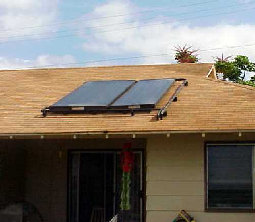
Figure 1.7 Flat-plate thermal solar collectors for providing hot water.(photo courtesy of DOE/NREL, Warren Gretz)
Flat-plate photovoltaic collectors contain an array of individual photovoltaic cells, connected in a series/parallel circuit, and encapsulated within a sandwich structure with the front surface being glass or plastic. Solar energy falls directly upon the photovoltaic cell front surface and produces a small direct current voltage, providing electrical energy to a load. Unlike thermal collectors however, the backside of the panel is not insulated. Photovoltaic panels need to loose as much heat as possible to the atmosphere to optimize their performance.
Like flat-plate thermal collectors, flat-plate photovoltaic collectors (panels) absorb both energy coming directly from the sun's disc, and diffuse and reflected energy coming from other directions. In general, flat-plate photovoltaic panels are mounted in a fixed position and tilted toward the south to optimize noontime and daily energy production. However, it is common to see flat-plate photovoltaic panels mounted on mechanisms that track the sun about one tilted axis, thereby increasing the daily output of the panels.
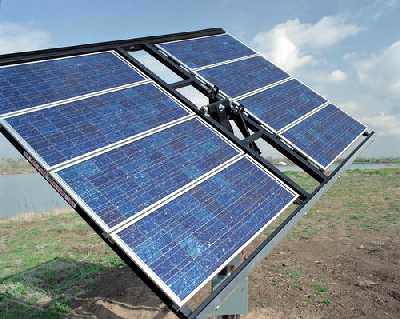

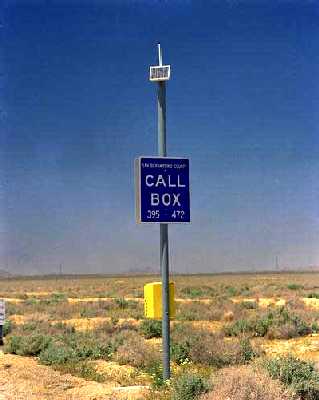
Figure 1.8 Flat-plate photovoltaic collector applications.(photos courtesy of DOE/NREL, Warren Gretz)
When higher temperatures are required, concentrating solar collectors are used. Solar energy falling on a large reflective surface is reflected onto a smaller area before it is converted into heat. This is done so that the surface absorbing the concentrated energy is smaller than the surface capturing the energy and therefore can attain higher temperatures before heat loss due to radiation and convection wastes the energy that has been collected. Most concentrating collectors can only concentrate the parallel insolation coming directly from the sun's disk (beam normal insolation), and must follow (track) the sun's path across the sky. Four types of solar concentrators are in common use; parabolic troughs (as used in the Kramer Junction, California solar energy electricity generating plant shown in Figure 1.1), parabolic dishes, central receivers and Fresnel lenses. Figure 1.9 shows these concepts schematically.
Figure 1.9 Three commonly used reflecting schemes for concentrating solar energy to attain high temperatures.
A parabolic trough concentrates incoming solar radiation onto a line running the length of the trough. A tube (receiver) carrying heat transfer fluid is placed along this line, absorbing concentrated solar radiation and heating the fluid inside. The trough must be tracked about one axis. Because the surface area of the receiver tube is small compared to the trough capture area (aperture), temperatures up to 400oC can be reached without major heat loss. Figure 1.10c shows one parabolic trough from the Kramer Junction, California field shown in Figure 1.1.
A parabolic dish concentrates the incoming solar radiation to a point. An insulated cavity containing tubes or some other heat transfer device, is placed at this point absorbing the concentrated radiation and transferring it to a gas. Parabolic dishes must be tracked about two axes. Figure 1.10b shows six 9kWe parabolic dish concentrators with Stirling engines attached to the receiver at the focus.
A central receiver system consists of a large field of independently movable flat mirrors (heliostats) and a receiver located at the top of a tower. Each heliostat moves about two axes, throughout the day, to keep the sun's image reflected onto the receiver at the top of the tower. The receiver, typically a vertical bundle of tubes, is heated by the reflected insolation, thereby heating the heat transfer fluid passing through the tubes. Figure 1.10a shows the 10 MWe Solar One central receiver generating plant at Daggett, California with its adjoining steam power plant.
A Fresnel lens concentrator, such as shown in Figure 1.10d uses refraction rather than reflection to concentrate the solar energy incident on the lens surface to a point. Usually molded out of inexpensive plastic, these lenses are used in photovoltaic concentrators. Their use is not to increase the temperature, but to enable the use of smaller, higher efficiency photovoltaic cells. As with parabolic dishes, point-focus Fresnel lenses must track the sun about two axes.
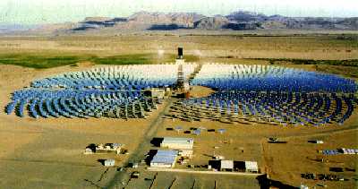
Figure 1.10a A central receiver system.
(courtesy of Sandia National Laboratories, Albuquerque)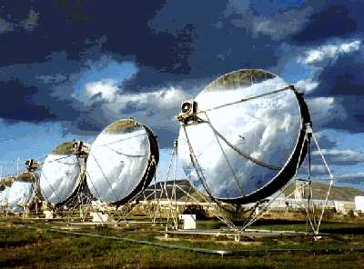
Figure 1.10b Two-axis tracking parabolic dish collectors.
(courtesy of Schlaich, Bergermann und Partner)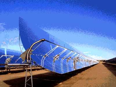
Figure 1.10c A single-axis tracking parabolic trough collector.
(courtesy of Kramer Junction Operating Company)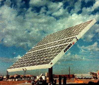
Figure 1.10d A concentrating photovoltaic collector using Fresnel lenses.
(courtesy of Amonix Corp.)Like with any other power plant, solar power plant output must satisfy the demands of the utility market. During peak demand periods, kilowatt-hour prices are high and financial incentives are high for guaranteed supply. Solar plant input is limited by diurnal, seasonal and weather-related insolation changes. In order to cope with these fluctuations, the solar plant input may be backed up by fossil fuels, or the solar changes may be mitigated by a buffering storage system. The choice depends on demands, system and site conditions, The relationship between storage capacity and collector area is discussed in Chapter 10.
In thermal solar power plants, thermal storage and/or fossil backup act as:
Photovoltaic plants in general need no internal buffer, and output management can be achieved with battery or other electrochemical storage, pumped hydroelectric storage, or with diesel-generator backup. The implications of battery storage are discussed in Chapter 10.
Figure 1.11 Stored solar energy provides a firm capacity of 31MW until midnight at which time fossil fuel backup us used.
Because of their thermal nature, all the solar thermal technologies can be hybridized, or operated with fossil fuel as well as solar energy. Hybridization has the potential to increase the value of concentrating solar thermal technology by increasing its availability and dispatchability, decreasing its cost (by making more effective use of power generation equipment), and reducing technological risk by allowing conventional fuel use when needed.
Although an interconnected field of solar thermal collectors and thermal energy storage may be sufficient for providing high temperature heat directly to a thermal demand, a power generation subsystem must be incorporated into the system design if mechanical work or electrical power is to be an output from the system. Chapter 11 reviews the technology for power generation with particular emphasis on power generation units suitable for interfacing with solar thermal energy collection subsystems. The inclusion of power generation in a solar thermal energy design presents a challenge in selecting the appropriate design conditions. The efficiency of a power generation unit usually increases with the operating temperature of the power generation cycle, whereas the efficiency of solar collectors decreases with temperature. A tradeoff must be performed to determine the best system design point.
Figure 1.12 One of the steam cycle power cycles at the Kramer Junction solar energy generating system.(photo courtesy of DOE/NREL, Warren Gretz)
Solar technologies using concentrating systems for electrical production require sufficient beam normal radiation, which is the beam radiation which comes from the sun and passes through the planet's atmosphere without deviation and refraction. Consequently, appropriate site locations are normally situated in arid to semi-arid regions. On a global scale, the solar resource in such regions is very high. More exactly, acceptable production costs of solar electricity typically occur where radiation levels exceed about 1,700 kWh/m²-yr, a radiation level found in many areas as illustrated in Figure 1.4. Appropriate regions include the southwest United States, northern Mexico, the north African desert, the Arabian peninsula, major portions of India, central and western Australia, the high plateaus of the Andean states, and northeastern Brazil. Promising site locations in Europe are found in southern Spain and several Mediterranean islands.
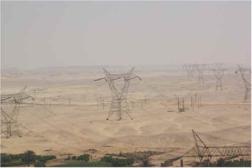
Figure 1.13 A View of Kuraymat (Egypt), the envisaged site for a solar thermal power plant in the Egyptian desert with cooling water from the
Nile and connections to the national high voltage grid.Solar electricity generation costs and feasibility of the project highly depend on the project site itself. A good site has to have a high annual beam insolation to obtain maximum solar electricity output. It must be reasonably flat to accommodate the solar field without prohibitive expensive earth works. It must also be close to the grid and a substation to avoid the need to build expensive electricity lines for evacuating the power. It needs sufficient water supply to cover the demand for cooling water of its steam cycle. A backup fuel must be available for granting firm power during the times when no solar energy is available. Access roads must be suitable for transporting the heavy equipment like turbine generators to the site. Skilled personnel must be available to construct and operate the plants. Chapter 13 reviews the criteria, methodology and examples of site selection and qualification for solar plants.
The most important factor driving the solar energy system design process is whether the energy it produces is economical. Although there are factors other than economics that enter into a decision of when to use solar energy; i.e. no pollution, no greenhouse gas generation, security of the energy resource etc., design decisions are almost exclusively dominated by the levelized energy cost. This or some similar economic parameter, gives the expected cost of the energy produced by the solar energy system, averaged over the lifetime of the system. In the following chapters, we will provide tools to aid in evaluating the factors that go into this calculation.
Commercial applications from a few kilowatts to hundreds of megawatts are now feasible, and plants totaling 354 MW have been in operation in California since the 1980s. Plants can function in dispatchable, grid-connected markets or in distributed, stand-alone applications. They are suitable for fossil-hybrid operation or can include cost-effective storage to meet dispatchability requirements. They can operate worldwide in regions having high beam-normal insolation, including large areas of the southwestern United States, and Central and South America, Africa, Australia, China, India, the Mediterranean region, and the Middle East, . Commercial solar plants have achieved levelized energy costs of about 12-15¢/kWh, and the potential for cost reduction are expected to ultimately lead to costs as low as 5¢/kWh.
Figure 1.14 Projections of levelized electricity cost predictions for large scale solar thermal power plants
. Current costs are shown in blue with a 1-2 cent/kWh addition for 'green' power shown in green.The authors' overall objective is to illustrate the design of solar energy systems, both thermal and photovoltaic types. To do this, we examine the solar resource and the ability of various types of solar collectors to capture it effectively. Design tools are developed which integrate performance of isolated solar collectors, along with energy storage, into a larger system that delivers either electrical or thermal energy to a demand. We show as many examples as possible, both graphic and photographic of these systems and their components.
It is our hope that once the simplicity of solar energy system design is understood, engineers and manufacturers will provide new system designs that will expand the solar market worldwide and permit all to benefit from this clean, sustainable and distributed source of energy.